


CHEK FHASE AUDIO
 04.41
04.41
 By
TIBET SOUND SYSTEM
By
TIBET SOUND SYSTEM


Check Phase schema
itu berarti salah satu speaker ada yang out phase(terbalik min plusnya)n kalo kasus seperti
itu masih bisa diatasi hanya membalik salah satu kabel saja sudah jadi,,walaupun posisi phase
di in phase atau out phase,yang benar di in phase,,lampu indikator nyala hijau pada alat.
Coba bayangkan kalo kita pasang speaker 5 saja kiri 5 kanan 5 sulit sekali kita mendeteksi
phasenya.
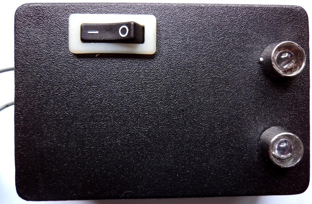
Saya akan menerangkan sedikit tentan cek phase,cek phase biasanya ada 2 item yaitu reciver gunanya untuk memonitoring hasil phase yang dihasilkan dari suara elektonik maupun acoustic.
Sedangankan transmiter adalah generator yang menghasilkan gelombang kotak yang di
masukan ke perangkat audio yang di teruskan ke loudspeaker.
Alat tersebut sudah populer di dunia engineering audio..(operator) tapi kalo sobat belum meamkai alat tersebut saya anjurkan harus beli.
Kenapa harus punya???alat tersebut vital sekali selagi sobat mempunyai banyak speaker
yang terpasanng ketika kita dapat job ngeson,nggak mungkin kita cek box demi box nengan telinga apakah phasenya dah betul ato belum.
Harga cek phase yang brandit cukup tidak terjangkau
Bulan depan saya ingin bagikan skema cek phase secara gratis...
Catatan: beda power biasanya beda phase
:beda sumber listrik biasanya beda phase
:tambah acesoris juga di cek phase ulang
:pemasangan cek phase setelah complit terpasang
:di line mixer audio
Cara pasang: tranmiter dimasukan mixer pada lin in,posisi tone flat.
:reciver di todongkan depan speaker pas tengah persis
Sekian..kalo ada susuna kalimat kurang bagus mohon maaf, salam...Skema cek phase


Bulan yang lalu saya sudah bahas tentang Cek Phase dan kali ini saya unggah skema Cek Phase yang
pernah saya janjikan,,dengan skema sederhana ini smoga bisa bermamfaat dan setidaknya untuk
wawasan
GAMBAR YANG SUDAH JADI DENGAN PCB LUBANG



Ic Cek Phase,bulan lalu sudah saya terangkan,penggunaan Cek Phase dan skemanya juga sudah saya unggah
kali ini saya berikan Type ic-nya.Sudah tau caranya sudah ada skemanya kok belum ada type-nya..lucu kan?
Mohon maaf pada rekan2 yang sudah mengikuti blog saya,,dan jangan lupa slalu kunjungi ya..kalau ada ilmu
baru pasti saya bagikan.
Typetype ic cek phase
IC.1-CD 4049
IC.2-CD 4093
IC.3-HEF 4027
catatan:pada zener dioda 5v.sedangakan type pembangkit pulse-nya CD 4093
Usahakan pada type HEF 4027 merk philip agar sempurna. IC
kali ini saya berikan Type ic-nya.Sudah tau caranya sudah ada skemanya kok belum ada type-nya..lucu kan?
Mohon maaf pada rekan2 yang sudah mengikuti blog saya,,dan jangan lupa slalu kunjungi ya..kalau ada ilmu
baru pasti saya bagikan.
Typetype ic cek phase
IC.1-CD 4049
IC.2-CD 4093
IC.3-HEF 4027
catatan:pada zener dioda 5v.sedangakan type pembangkit pulse-nya CD 4093
Usahakan pada type HEF 4027 merk philip agar sempurna. IC





 Postingan


