booster circuit is used to enanching or boosting or increase the
subwoofer amplifier, but it also can improve the quality of the bass sound on an
amplifier or
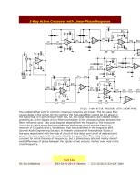
High Power Amplifier. Subwoofer booster circui /
bass enhancer circuit based on the IC 4558 and TL074 or commonly known as IC
op-amp , its suitable to be an boosting in subwoofer system, which together with some components.
For this subwoofer booster / enhancher circuit using
voltage of 12 V + , 12V - , and ground. To be in accordance with the power of the
speakers and
amplifiers , the Subwoofer booster circuit / subwoofer enhancer is also equipped with
a subwoofer
volume setting on the R9 and R12 use 20 K ohm trimpot. Issued a circuit
of subwoofer output is quite high , making it suitable for some
speakers.
 |
| Subwoofer booster circuit |
Part List :
- See more at: http://circuitschematicelectronics.blogspot.com/2011/03/subwoofer-booster-circuit.html#.Uj0MElPKHXQ
booster circuit is used to enanching or boosting or increase the
subwoofer amplifier, but it also can improve the quality of the bass sound on an
amplifier or
High Power Amplifier. Subwoofer booster circui /
bass enhancer circuit based on the IC 4558 and TL074 or commonly known as IC
op-amp , its suitable to be an boosting in subwoofer system, which together with some components.
For this subwoofer booster / enhancher circuit using
voltage of 12 V + , 12V - , and ground. To be in accordance with the power of the
speakers and
amplifiers , the Subwoofer booster circuit / subwoofer enhancer is also equipped with
a subwoofer
volume setting on the R9 and R12 use 20 K ohm trimpot. Issued a circuit
of subwoofer output is quite high , making it suitable for some
speakers.
|
| Subwoofer booster circuit |
Part List :
R1 = 22K
R2 = 100K
R3 = 220R
R4 = 220R
R5 = 220R
R6 = 10K
R7 = 4K7
R8 = 1K
R9 = 20K Trim
R10 = 150K
R11 = 22K
R12 = 20K Trim
R13 = 4K7
R14 =2K2
R15 = 220R
R16 = 220R
R17 = 180K
R18 = 22K
C1 = 4u7/25V
C2 = 10uF/25V
C3 = 220uF/25V
C4 = 220uF/25V
C5 = 1n2
C6 = 47n
C7 = 47n
C8 = 100n
C9 = 100n
C10 = 4u7/25V
C11 = 330uF/25V
C12 = 330uF/25V
IC1 = JRC4558
IC2 = TL074
- See more at: http://circuitschematicelectronics.blogspot.com/2011/03/subwoofer-booster-circuit.html#.Uj0MElPKHXQ


1 komentar: